Slicing Parameters:
Open source slicing software have built-in extensive documentation. Direct links to printing parameters documentation for the popular slicers
Orca slicer (opens in a new tab)
PrusaSlicer (opens in a new tab)
My recommendations using my preferred slicer Orca slicer D.James
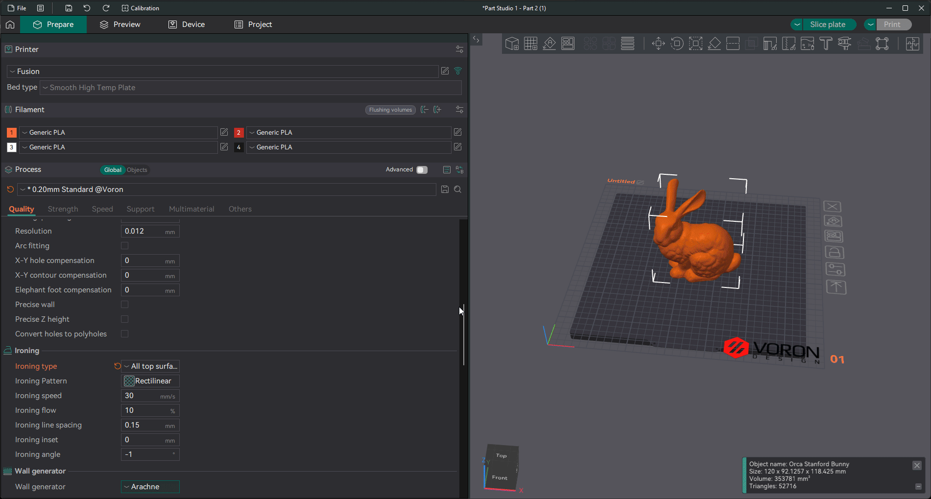
Quality
-
Layer height: 0.2 mm
-
First Layer height 0.2 mm
Line Width
-
In most cases I update these to 0.6 mm this is 120% of the nozzle size and can reduce print time and increase strength.
-
For detail and text I leave the default settings.
Seam Position
-
Aligned / Rear
-
Scarf joint on all seams.
Wall Generator
- Arachne
Walls and surfaces
-
Inner/Outer/Inner
-
Small area flow compensation(beta)
Bridging
-
Thick external bridges
-
Thick internal bridges
-
Extra bridge layers(beta)
Bridge counterbore holes
- Sacrificial layer
also helps with support removal.
Overhangs
- Extra perimeters on overhangs.
Strength
Wall Loops:
I increase this for desired strength.
-
Wall Loops : 3
-
Alternate Extra Walls
Top/Bottom Shells
-
Top shell layers: 5
-
Top shell thickness: 0 mm
This dissables the thickness limmet and uses the number of layers instead. 5 0.2 mm layers = 1 mm thick
- Top surface pattern: Monotonic Line
Depending on the model and desired top surface finish. These can be interesting to play with.
-
Bottom surface pattern: Monotonic Line
-
Bottom shell thickness: 0 mm
This disables the thickness limit and uses the number of layers instead. 5 0.2 mm layers = 1 mm thick
- Bottom surface pattern: Monotonic Line
Infill
- Sparse infill density: 10%
Again, depending on desired strength. the majority of model strength is derived from the wall not the infill.
- Sparse infill pattern: Gyroid
Personal: use for most models. Lightweight and quick models use adaptive cubic.
- Infill combination
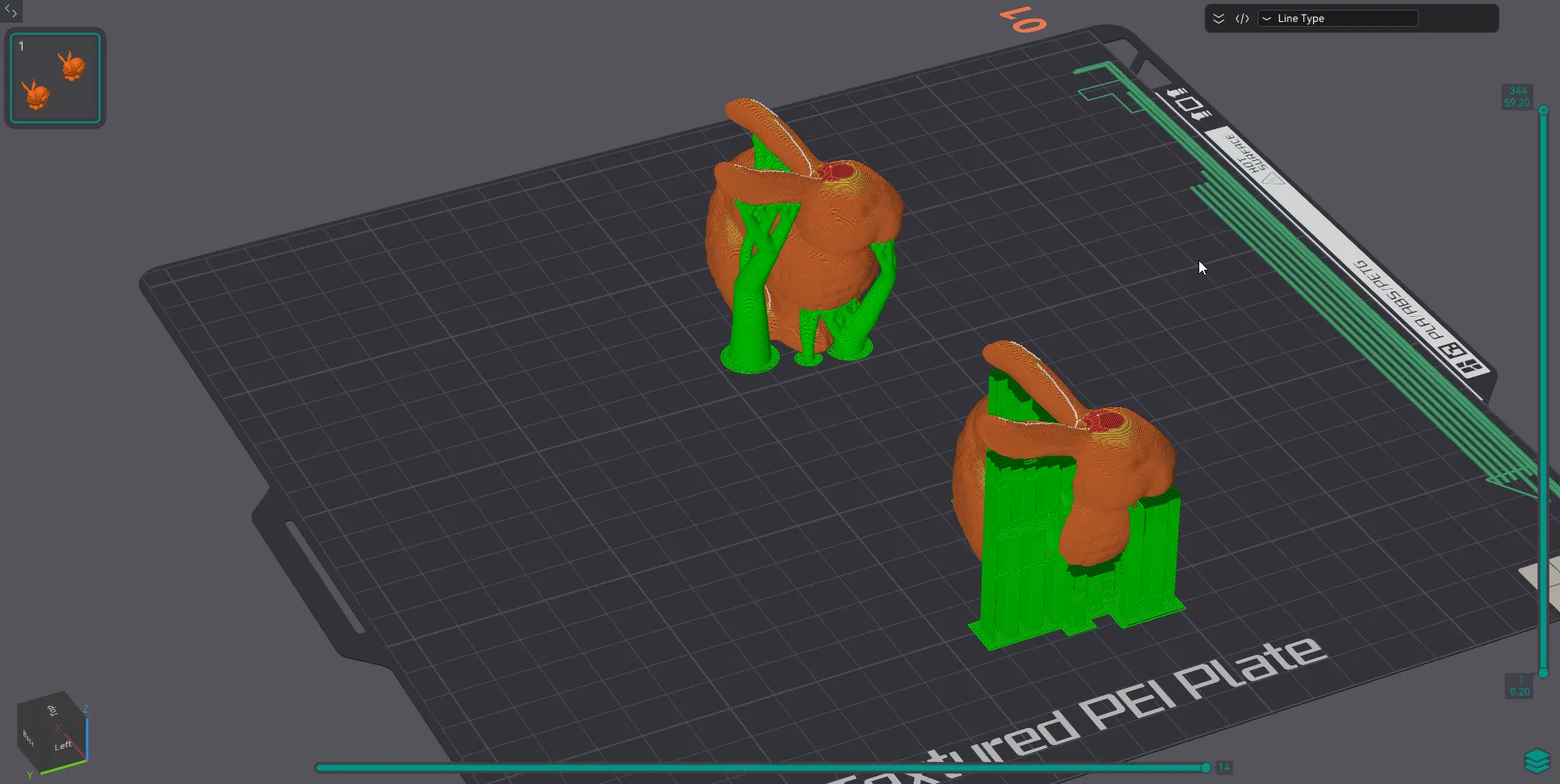
Supports
I avoid using supports as much as possible, however when I do I use the following settings. The following is my thougtht process:
Identify the areas needing support
- is the area a direct line from the build plate?
- is the area not in a direct line to the build plate?
If the supports do not need to be routed around other parts, I prefer standard supports.
If the model requires significant support, I refer tree supports.
If the model is printed in PLA and I have a multi material system available, I will change the support interface layer to PETG
-PLA will not bond to PETG, this allows for easy removal of the support interface layer.
If you attempt to use PETG with PLA supports, the PLA may JAM your hotend.
Others
- Brim type: Mouse ear (if needed)
This places small tabs on sections of a print that may lift due to internal tension. These are very easy to remove.
-
Verbose G-code
-
Label objects
-
Exclude objects
if the printer supports the feature, during the print of multiple models, this feature allows you to skip a model that failed and continue printing the other without losing progress.